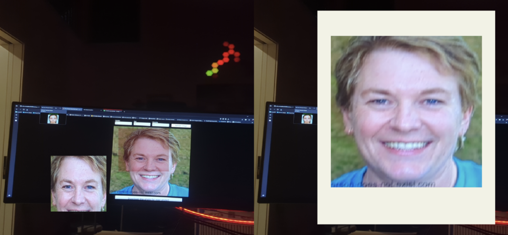
The Veil needs a way for the wearer to see out while an outward-facing screen covers their face. This is a fairly important feature. Without it, I am building an expensive way to walk into furniture.
The earlier phone-based approach got the project moving, but it also put a whole phone in front of my face. The next step is a dedicated pair of displays, lenses and a stereo camera. All of this hardware needs somewhere to live.
So I started designing glasses.
They got a little out of hand.
ELTON JOHN MEETS THE PARTS BIN

The initial direction was oversized 1970s eyewear. Big frames, big lenses, absolutely no chance of being mistaken for something subtle. I worked through a hand sketch, a form sketch in Nomad and component layouts in Rhino.
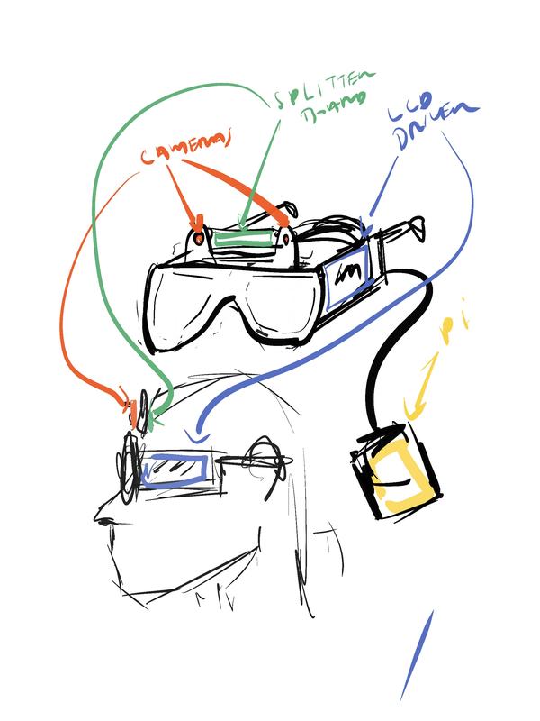
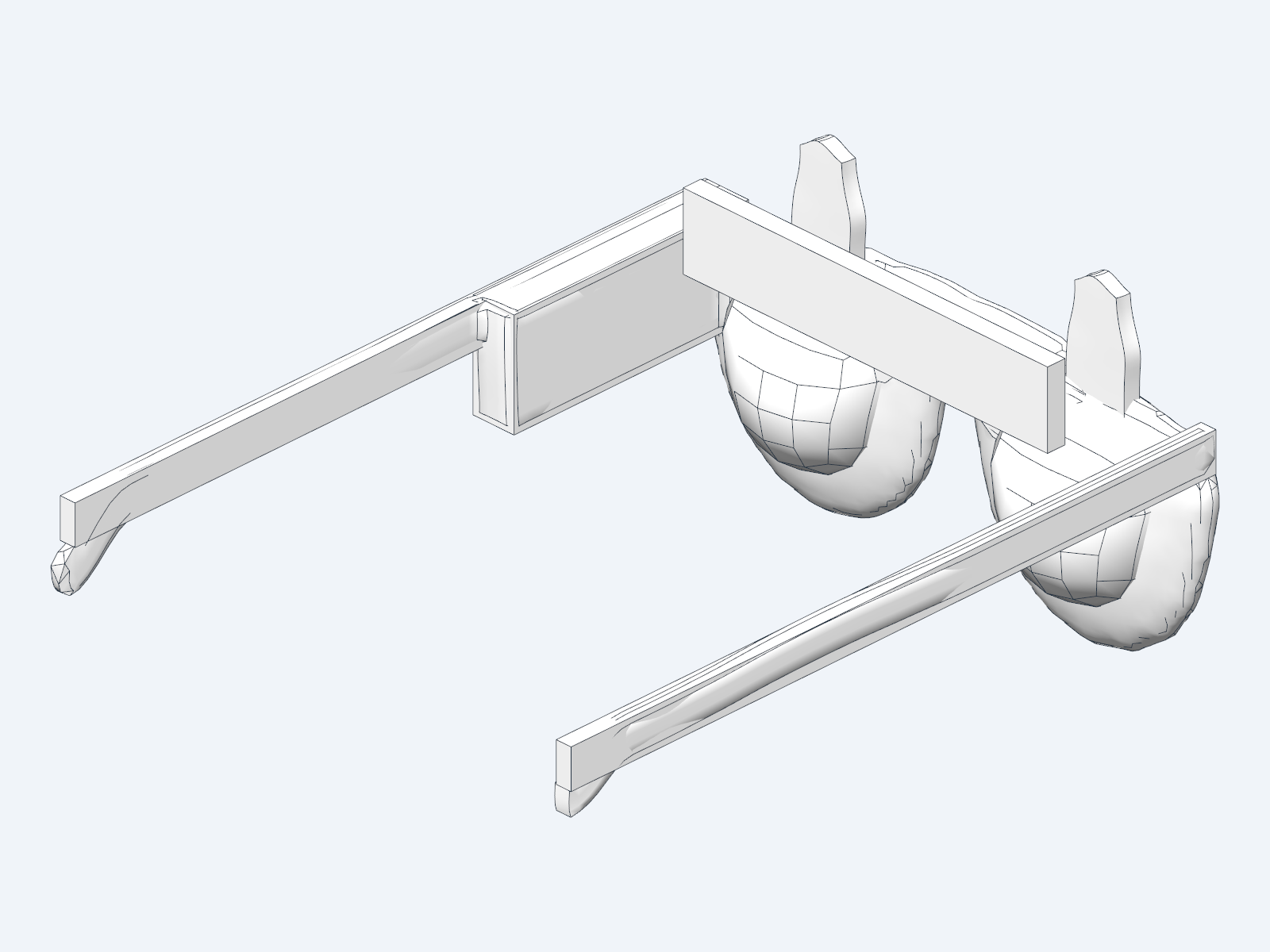
The sketches have one major advantage over the actual hardware: they don’t need cables.
In Rhino, the LCDs, optical stack, driver board and splitter board were laid out at scale. These components set the terms. I could change the frame around them, but shrinking a board until it looked better would be cheating. It would also make for a very disappointing afternoon when the parts arrived at the printer.
The design moved toward an exposed, triangulated structure. Angular braces, visible mounting points, a cage for the camera. Somewhere between ridiculous glasses and the skeleton of a helmet.
This feels appropriate for Veil. A project about surveillance and identity probably shouldn’t look like another anonymous black plastic appliance. I want the machinery to be part of what people see.
EVERYTHING NEEDS A BRACKET
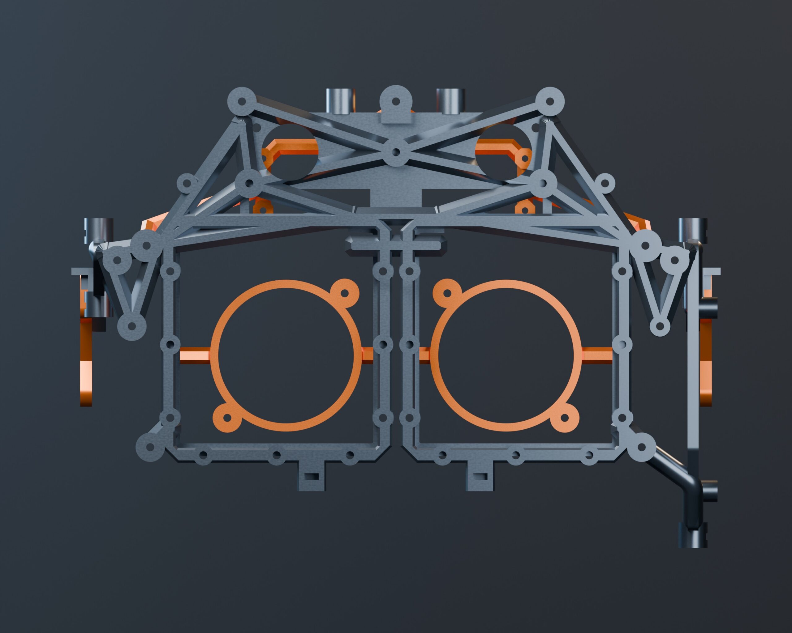
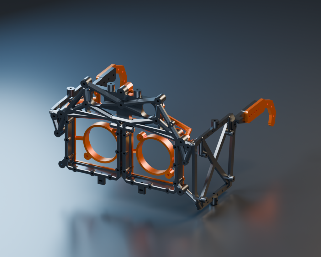
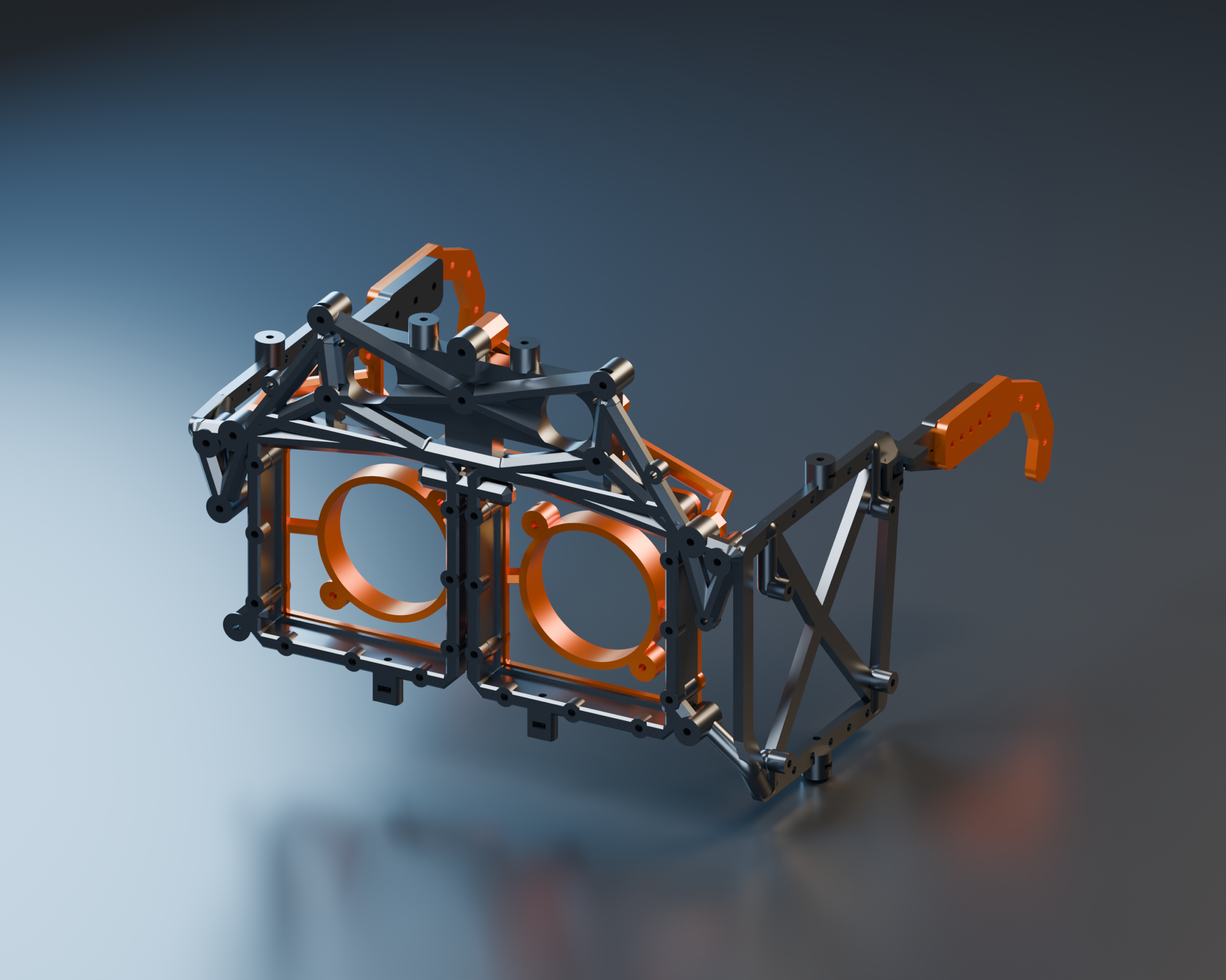
The current chassis holds the two LCD optical assemblies, the stereo camera, the LCD driver and the splitter board. The driver sits on the right side. The left side gets a lighter structure because making both sides equally bulky would solve a problem I don’t have.
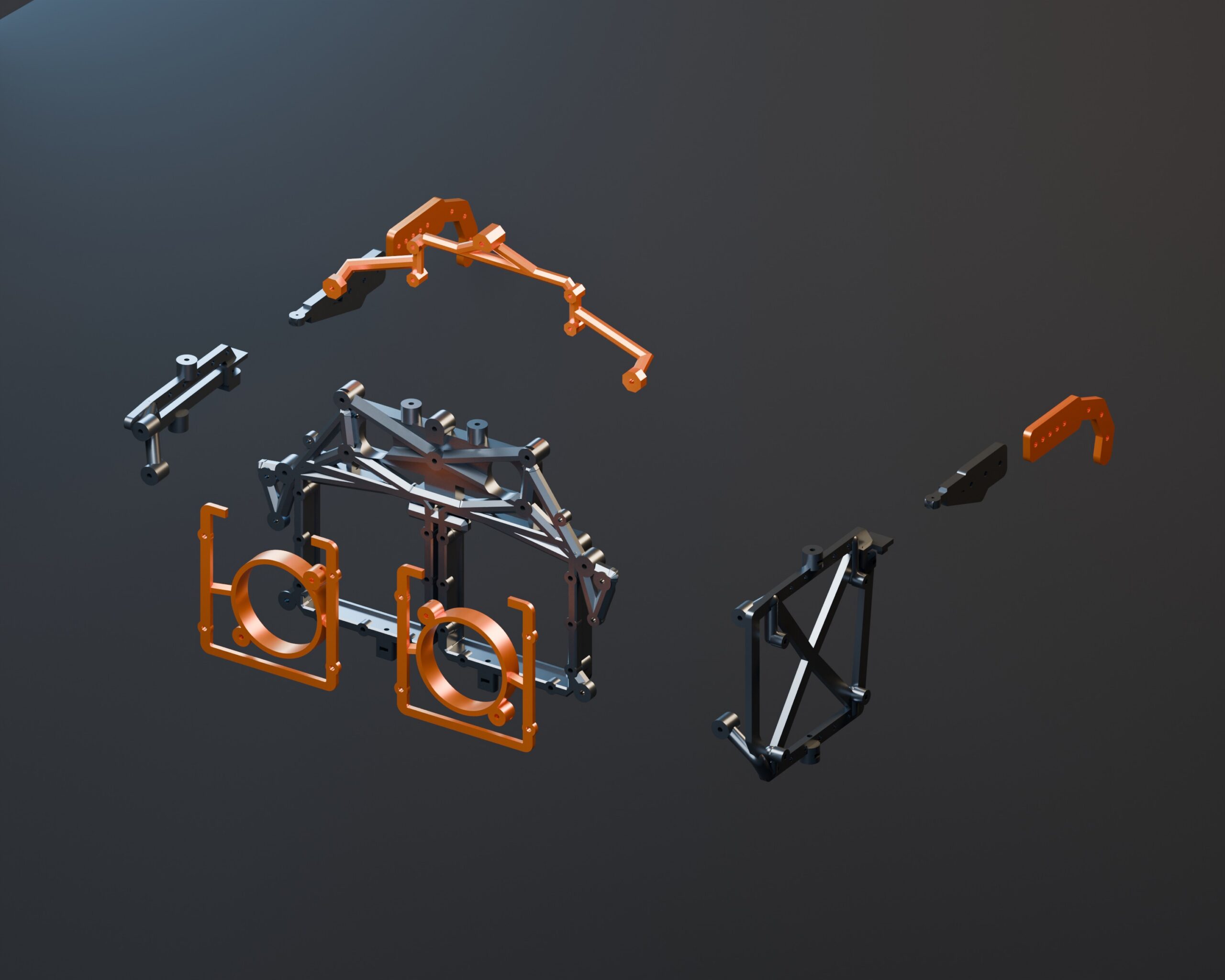
The front frame and side carriers bolt together. The lens retainers come off. The splitter has its own removable mount with a faceted Y brace. There are M2 accessory mounts around the chassis for whatever the next version decides it can’t live without.
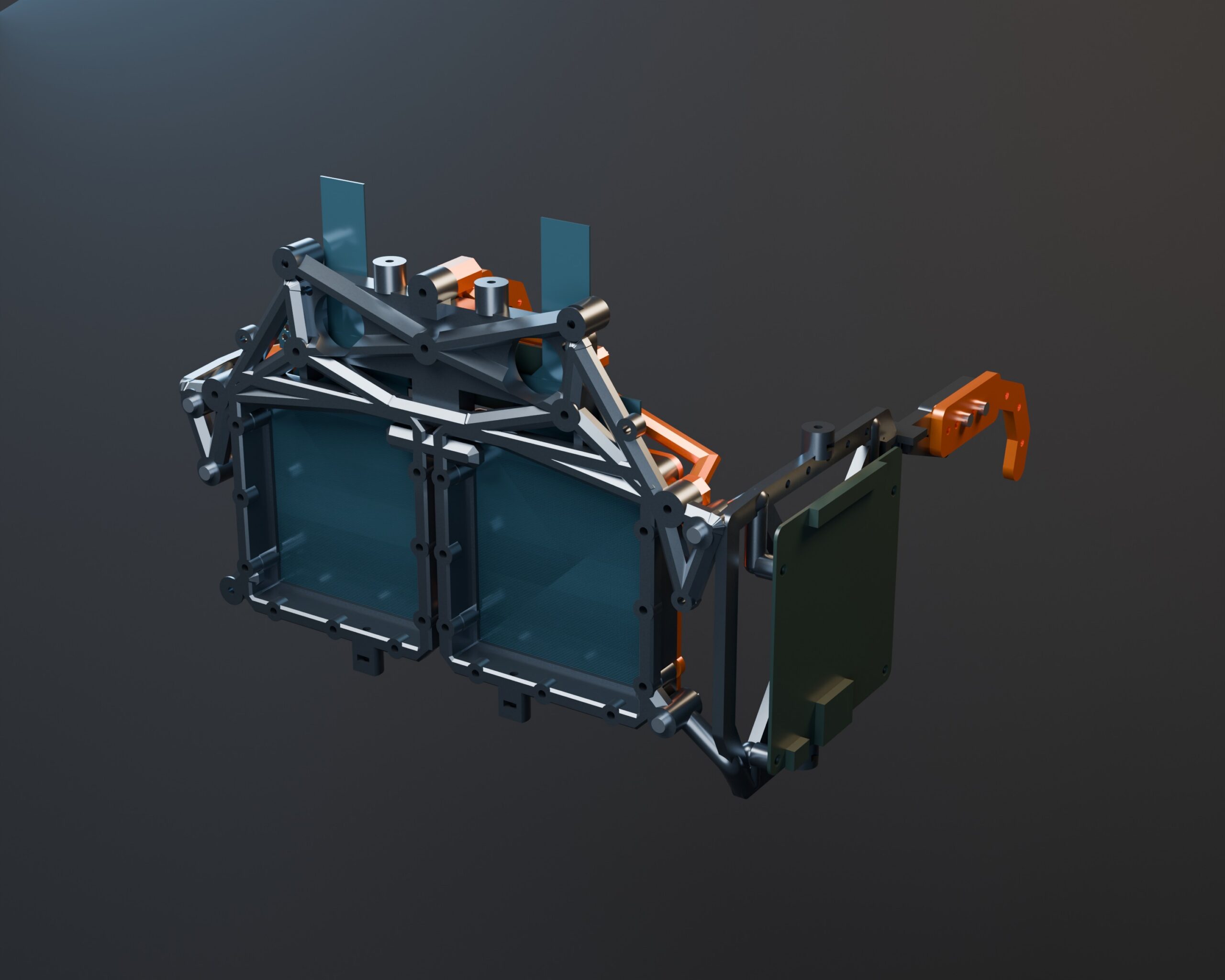
There are ten separate chassis parts in the current export:
- One front chassis with the camera cage.
- Two lens retainers.
- Two side carriers.
- Two hinged arms.
- Two adjustable ear hooks.
- One bolt-on splitter frame.
Ten parts sounds like a lot for glasses. It is. But if one bracket needs to change, I’d prefer to replace that bracket rather than reprint the entire contraption. Being able to get the electronics back out is also useful. I suspect I will want to do that more than once.
YES, THEY FOLD
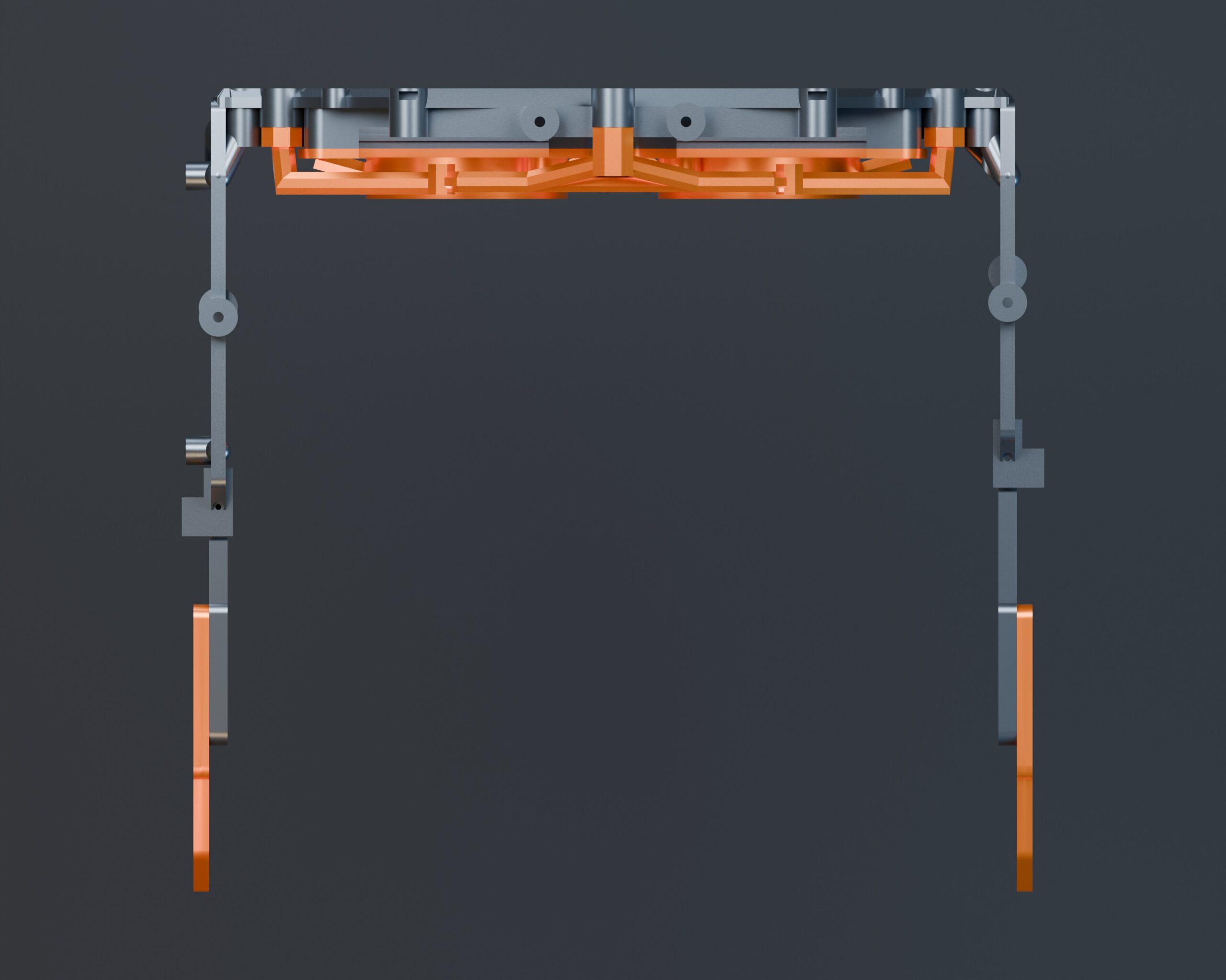
The arms use little M1 screw hinges. The ear hooks have three length settings: standard, plus 5mm and plus 10mm. Two bolts clamp each adjustable end in place.
One hinge sits 10mm farther back than the other so the extended ear hooks can pass each other when folded. Symmetry is nice. Parts occupying the same space is less nice.
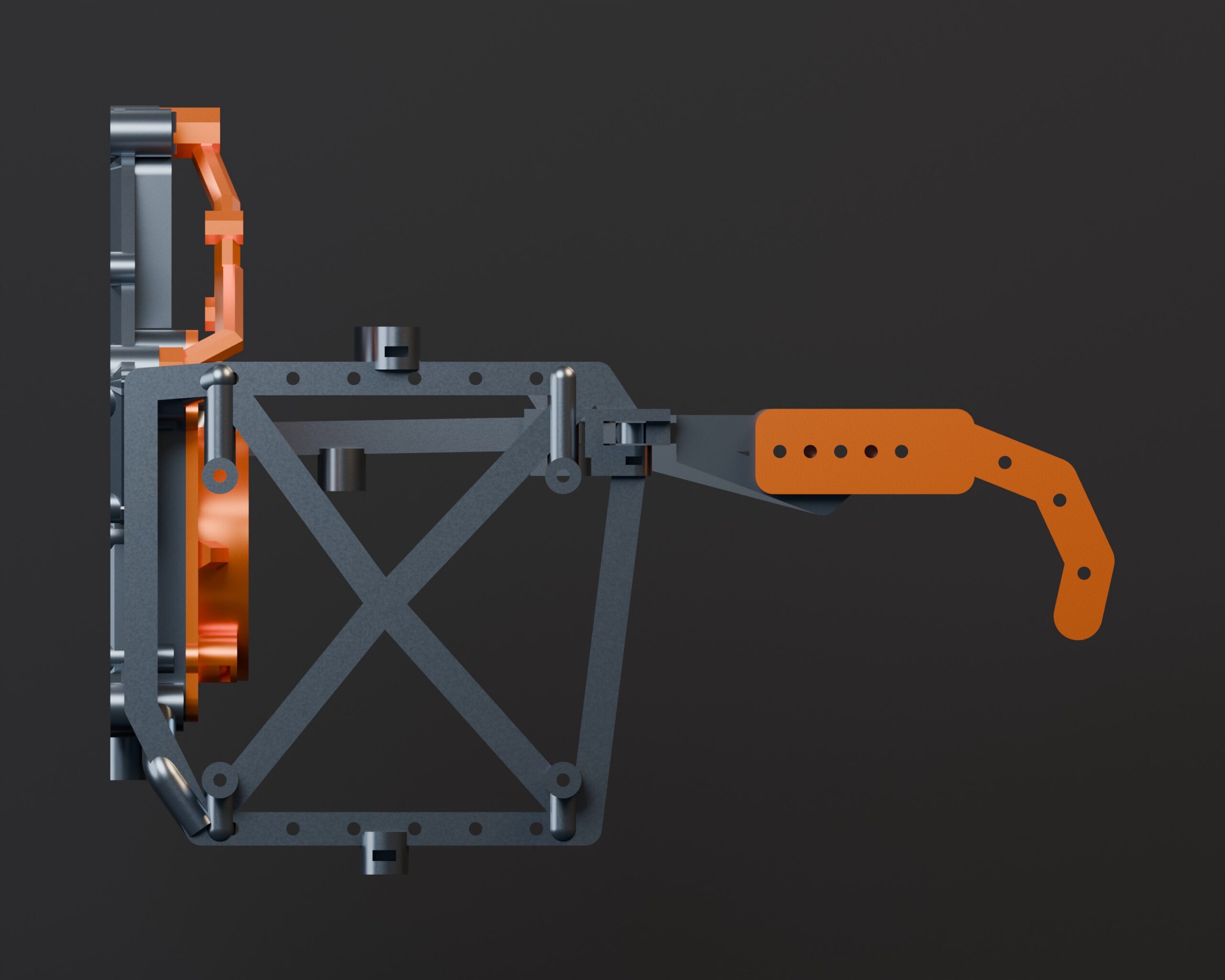
This is the sort of thing that doesn’t show up in the original sketch. Draw two arms. Add hinges. Fold them. Discover that the ends want to be in the same place. Move one hinge. Try again.
Repeat for boards, braces, screw holes and the places where a nut needs to go.
DRAW ON IT. SEND IT BACK.
A large part of this process has been working back and forth with Codex, Rhino and text-to-cad. I supply the component drawings, references and design direction. Codex turns those into the parametric model. Then I look at it and start drawing on the screenshots.
Rhino is part of that conversation, too. I work in the actual document, drawing the components at scale and working out their placement. Through the Rhino MCP connection, Codex can inspect the objects and dimensions in that document. I can draw something and have it look at what I actually drew, rather than try to explain the whole thing in a chat message.
That gave us a way to carry the measured board outlines, mounting holes and component geometry into the chassis model. Rhino was also a place to bring the STEP geometry back for review or further editing. I wasn’t handing over a sketch and waiting for a finished product; I was moving between drawing, modeling and reviewing while Codex worked from the same material.
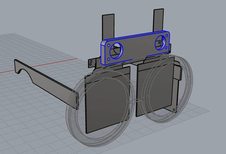
The Y-pipe is a good example. I designed that piece in Rhino, and we used it as a reference while developing the splitter support. The later faceted brace changed its appearance, but the starting geometry came from my modeling work. Some changes started with a marked screenshot; others started with an actual part I had drawn.
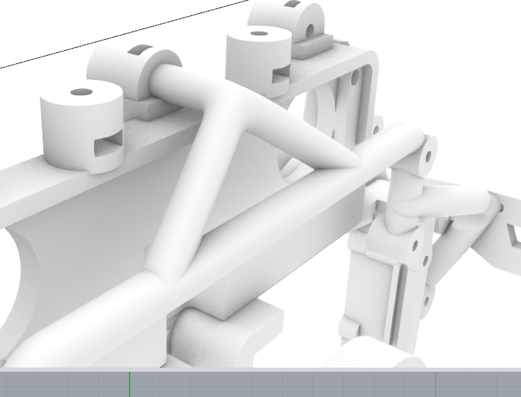
Move this boss over here. Extend this brace. Get rid of that lump. Why does this joint look like somebody took a bite out of it?
The text-to-cad viewer gives us a common object to argue over. I can rotate the model, take a screenshot and mark the exact part I want changed. A pink line or a circle is often a lot more useful than trying to describe the third cylinder from the left, behind the other cylinder, assuming we are both looking at the same left.
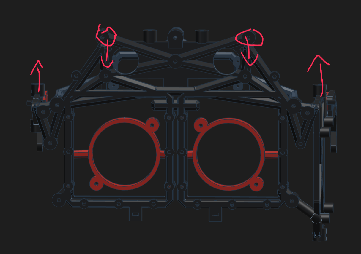
Codex revises the geometry, rebuilds it and checks the affected holes, joints or clearances. I review the next version. Sometimes the change does what I wanted. Sometimes seeing it in 3D makes it obvious that I wanted something else.
We used this loop to move mounting bosses, clean up brace intersections, sharpen the camera cage and work through the detachable splitter mount. The marks are quick; the resulting changes still have to become actual geometry.
This is where the workflow gets useful for me. I can work visually, with measured drawings and scribbles, while Codex handles much of the repetitive construction and checking. I still have to decide whether the thing looks right and whether it makes sense. And neither of us gets to tell the printer that the screenshot looked fine.
THE COMPUTER SAYS IT FITS
The mechanical model is now parametric Python/build123d, using text-to-cad. Rhino supplied the component geometry; the script builds the chassis around it. This makes it possible to change a dimension and rebuild the related parts instead of manually chasing the same edit through a pile of geometry.
It also makes checking the less exciting stuff easier. Are the solids valid? Is that screw hole actually open? Did a brace grow through a board? Can the separate carriers meet the front frame without overlapping it?
The latest STEP export contains ten valid solids. Focused geometry checks cover the splitter attachments, camera brace and lens supports. This is useful progress.
It is not the same as putting the thing on my head.
LOOKS FINISHED. ISN’T.
I rendered the chassis in Blender with graphite and orange anodized-metal finishes. The lighting is good. The orange looks great. There are no stray cables ruining the shot.
The first prototype will be PLA.
The images show the design and a possible finish, not a completed metal headset. The outward-facing face display and the rest of the Veil system are beyond this chassis pass. There is still plenty of work between a convincing render and something I can actually wear.
Next up: slicer review, a physical fit print, actual fasteners, actual boards and actual cables. The full camera body needs to be checked against the cage. The hinges need to move in plastic. The arms need to fit a human head. Preferably mine.
For now, the design pass is complete and paused for prototyping. I have ten parts and a nice picture.
Time to find out what I got wrong.